Conductor of Electricity♯
My name is Andrew Kilpatrick and I've been building electronics and writing
code since I was a kid. Most of my career has been involved in developing music,
audio and multimedia electronics. I enjoy working on complete designs from the
initial idea all the way through to production. When I'm not coding or designing
electronics I enjoy making music and teaching others about technology. I live and
work in Montreal Canada.
If you want to hire me or hang out and chat about music, audio, radio or electronics,
you can always get in touch with me!
Work Objectives
My main objective in my work is to create technology products for music, audio and
media that are inspiring and bring new capabilities to creators and others involved
in the media industries.
I am very experienced in the following areas:
- hardware product design and prototyping - concept to production,
application design, 3D CAD
- electronics design - analog and digital audio, musical instrument,
embedded Linux and microcontroller firmware, high-speed interfaces, video
- audio - analog front-ends, preamps, audio conversion, I2S, TDM, S/PDIF,
AES3, network audio, streaming, effects, synthesis, USB audio and MIDI
- embedding programming - embedded C/C++, DSP programming, Linux,
ARM Cortex, PIC, FPGA, OpenGL, protocol drivers such as USB and
Ethernet, power management, and more
- application development - Java, C and C++ development for
applications mostly on Linux - some GUI development experience
but prefer to work on low-level code, protocols, server stuff, etc.
- design for manufacture - part sourcing, contract manufacturing,
enclosure design, BOM, test procedures, shipping and logistics
♯ It's a double-entendre.
Additional Skills and Interests
Music
I am a classically-trained violinist and vocalist having studied
violin from age 3-18, and singing at both the conservatory and
university levels. I currently enjoy playing violin, guitar,
singing and composing music in my private studio as part of my
work developing electronic music equipment.
Audio and Video Production
Since age 12 I have been active in live and recorded audio
production, lighting and technical theatre. I worked for many
years in live audio production mixing sound and working on the
technical crew for many theatre and music shows, festivals and
corporate shows. I am comfortable at the mixing console, on the
fly floor, building sets or coiling cables. During my younger
years I made many live concert recordings and demos
for local bands.
These days my work in audio is mostly related to my own music
and video productions, as well as the monthly
Synth Society Montreal
meetup group that I host in Montreal.
Technology Education
Teaching others about technology is one of my passions. I have
given classes and individual instruction in electronics and
programming. You can see my current YouTube videos
on electronics and music technology. My video series about MIDI
has become a go-to resource for musicians and developers alike.
Amateur Radio
I became a licensed amateur radio operator in Canada when I was
13. (Basic with Honours) This was my first introduction to
formal electronics training. Several years ago I obtained my
Advanced license and am working on many hobby radio projects.
My amateur radio callsign is VE2EOT.
Selected Development / Design Portfolio
I am a multi-disciplined designer combining my extensive experience in audio, music, electronics and programming to create to create unique designs of the highest calibre. With experience in analog and digital electronics, audio, embedded programming, Linux, 3D CAD, enclosure design and related areas, I have the skills to take an idea from a concept through to production.
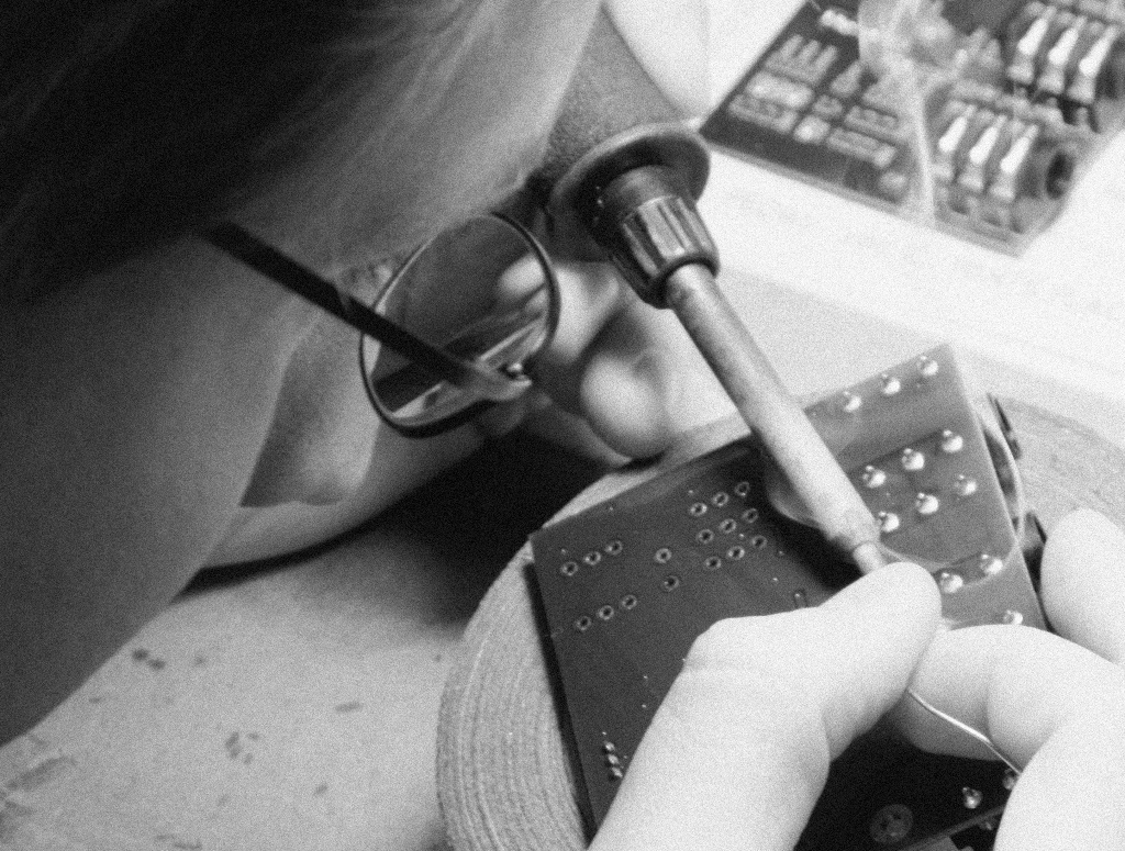
Unlike many designers, I have experience not only designing products, but also dealing with manufacturing. My projects have included procuring custom parts, handling finances, dealing with logistic and off-shore manufacturing. I also have hands-on experience with through-hole and surface-mount assembly and current run a small SMT assembly line in my workshop complete with stencil printer, pick-and-place machine and reflow oven. The bottom line is that I understand both the technical and business challenges involved in bringing a new idea to market.
Vocalami Personal Monitor (Kilpatrick Audio) - 2021
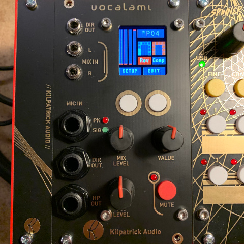
To further my personal goals as a vocalist, I developed Vocalami. It is a new kind of audio module that combines a microphone preamp, headphone monitoring system, audio effects and mixer into a surprisingly small Eurorack module. It sounds great and is easy to use when performing. It solves the main problem of the vocalist which is that of monitoring.
Vocalami is currently in the prototype stage.
Virtue Eurorack USB MIDI Controllers (Kilpatrick Audio) - 2021
Bridging the gap between hardware and software music tools, the Virtue series of USB MIDI controllers in Eurorack format are the first of their kind in the industry. Combining the flexibility of a modular synthesizer with the immense power of the computer for music and audio production allows users to create the control surface that best suits them. I developed Virtue as a response to my interest in virtual modular synthesis. After many years using only hardware synthesizers, I have come to appreciate some of the benefits of computer-based modular system: small size, flexibility, processing power and patch storage. Virtue adds the necessary hands-on tactile feel in a format the allows users to pick and choose the right combination for their performance style.
Virtue initially launched in 2021 with four types of controllers, a Eurorack USB 2.0 high-speed hub, and two sizes of desktop Eurorack enclosures to allow full systems to be built. The product even launched with a custom plugin for the VCV Rack virtual modular synthesizer software to allow direct mapping of controls from software to the hardware.
Find out more about Virtue
VCV Rack Plugins (Kilpatrick Audio / Dintree) - 2020
To make the best of a difficult year for manufacturing during 2020, I decided to learn to develop plugins for the VCV Rack virtual modular synthesizer platform. To date I have created more than two dozen modules and am working on a number of new ideas as well. Some of the modules I've realease are clones of my own hardware designs.
A few of the modules produced during this exploration are available for purchase or download including the following:
Radiator Laser Synthesizer (Neon Captain) - 2019
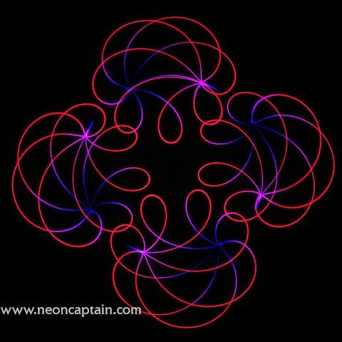
After seeing a classic planetarium laser light show as a child, I have always had a fascination with lasers. But until recently the cost of good laser equipment has been prohibitive. Advances in laser diode technology has enabled high quality laser light show projectors to be built at a low cost.
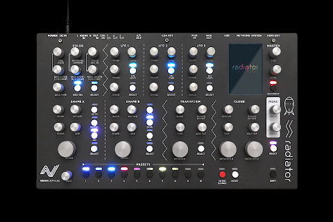
Despite the origins of the laser light show being that of a live performance art, advances in computer technology quickly turned the craft into more of a cinema than a live art form. The goal of Radiator was to bring back the hands-on and spontaneous nature of classic laser light shows using the latest advances in embedded hardware. Radiator is a virtual analog synthesizer designed for light instead of sound.
Through collaboration with one of the world's top abstract laser artists Christopher Short, I designed and implemented the Radiator laser synthesizer which was successfully crowdfunded on Kickstarter and completely sold out within months of becoming available. Radiator consists of custom hardware, firmware and an embedded Linux computer running the Radiator application. I designed the enclosure, electronics, firmware, application code and handled the production of the product.
Radiator won the 2020 Fred Fenning Technical Achievement Award from the International Laser Display Association!
Find out more about Radiator
REDOX Stereo Reverb (Kilpatrick Audio) - 2018
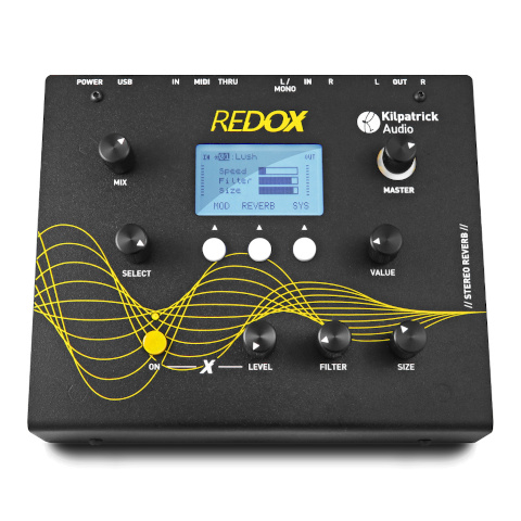
With the desire for compact and portable effects tailored towards electronic music, I developed the REDOX Stereo Reverb unit. This is the culmination of many months of research into digital reverberation which included the development of machine-learning models to improve the tuning of reverb algorithms. REDOX runs on a reusable audio platform I developed which has formed the basis for other projects and prototypes.
REDOX combines over a dozen digital reverb algorithms with other unique effects that can be combined to make unusual sounds. The device is designed to sit on the table and accepts stereo line inputs and outputs making it perfect for use with analog synthesizers.
Find out more about REDOX
TUNGSTEN Hand-held Music Computer (Kilpatrick Audio) - 2017
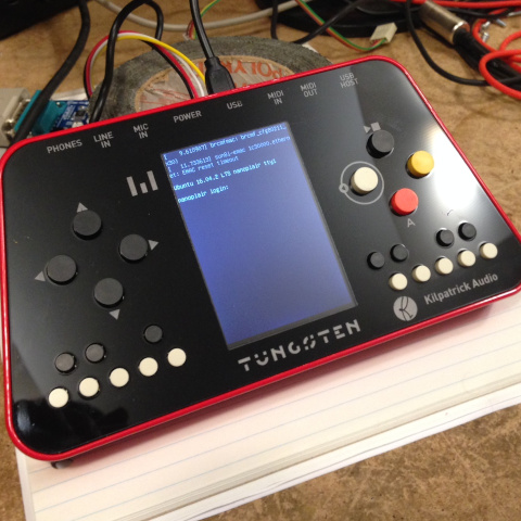
I became fascinated with chiptune music in 2016 and was inspired by composers using minimal retro computers and gaming devices to create music. With the emergence of low-cost embedded Linux platforms I developed the TUNGSTEN handheld music computer. It is housed in a beautiful machined aluminum enclosure with hardware audio and MIDI ports, Wi-Fi, a 3.5" colour LCD screen and internal rechargeable battery.
The concept was to present a complete music computer with an open architecture that anyone could develop programs for. The hope was that it would become popular in some electronic music genres and provide the basis for new exploration. Since the hardware was new and able to run code developed using modern techniques, this would allow anyone to own one and develop applications for it.
TUNGSTEN was presented at Superbooth 17 but did not enter production
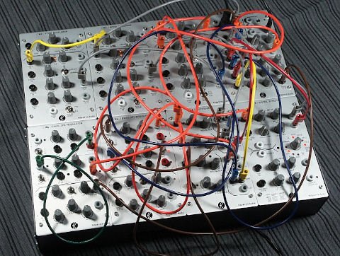
Analog-focused Eurorack Modules (Kilpatrick Audio) - 2016
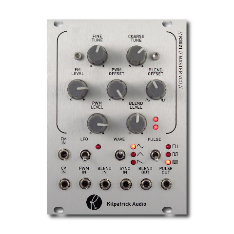
Based on the success of PHENOL patchable analog synthesizer, I was asked to provide some of its unique features in Eurorack format. I combined some of the features from PHENOL with newer versions of previous designs to create a full analog voice concept consisting of four modules: a VCO, filter, VCA and envelope generator.
Additionally, since the classic K3020 Dual VCO module had been out of production due to obsolete parts, the K3021 Master VCO was designed as the VCO. Since the main oscillator core of the K3020 was provided by a chip no longer available I designed a discrete replacement which matched the voltage levels, performance and sound of the original as closely as possible.
Find out more about Kilpatrick Audio Eurorack Modules
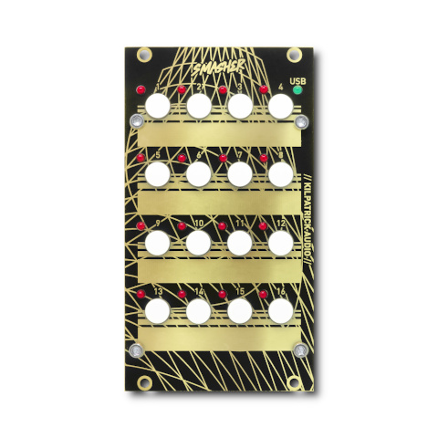
CARBON Sequencer (Kilpatrick Audio) - 2016
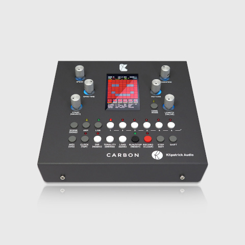
Since the release of the K4815 Pattern Generator module I have been asked for similar products with more features. After experimenting with several simpler sequencer concepts such as the K7 Entropy Sequencer and K2579 Step Sequencer, I developed CARBON. It combines the features of a pattern generator, step sequencer, arpeggiator, song sequencer and a number of other functions into a single table-top performance unit.
CARBON is my first hardware product to have completely open-source firmware which anyone is free to modify.
Find out more about CARBON
PHENOL Patchable Analog Synthesizer (Kilpatrick Audio) - 2015
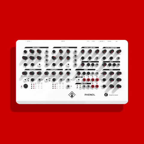
The PHENOL patchable analog synthesizer was a huge step forward in the world of modular synthesis at the time of its release. It was the first modular synthesizer (not semi-modular) to be offered at a price under $1000 USD ready to go out of the box. It was also the first serious table-top system to be released during the 2010s and literally paved the way for the Moog Mother-32 and most stand-alone synths that followed. Since its release no synth has managed to offer the same flexibility and combination of features.
PHENOL took many of the concepts developed for the Kilpatrick Format synthesizer such as the use of stacking banana cables, colour coded jacks and the universal use of bi-polar control voltages and put them into an attractive and affordable package.
PHENOL was a Kickstarter Staff Pick and more than doubled its funding goal!
Find out more about PHENOL
Numark NV DJ Controller / Akai Advance Keyboard (InMusic) - 2013-2014
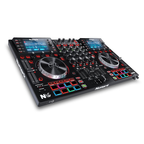
During 2013 I was brought on as the first hire of a Toronto-based team for InMusic. (owner of many brands such as Numark, Akai, M-Audio, Alesis, etc.) Our team was tasked with using new technology to develop several products including the Numark NV DJ Controller, and the Akai Advance line of keyboards.
My tasks involved board bring-up and embedded firmware for these devices. I developed USB audio and MIDI device drivers as well as graphics code and many other components.
Subpac Tactile Bass System (Subpac) - 2012
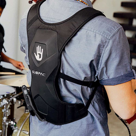
I developed hardware for the first version of the Subpac tactile bass speaker developed in Toronto by a team of artists and engineers. Initially brought on as a consultant I ended up being hired to design the entire electronics package which involved battery management, audio amplifier and audio processing conforming to very specific requirements from the design team. The product was successfully funded via Kickstarter and modern versions based on my original design continued to be sold for many years.
KFormat Modular Synthesizer System (Kilpatrick Audio) - 2012
As a response to issues found with the Eurorack format while developing modules, and inspired by larger modular formats such as Serge and Buchla, I developed the Kilpatrick Format (KFormat) in 2012. With a goal to provide the most solid and reliable format for building modules possible, KFormat went back to basics and reimagined what a modular system could be. The system initially launched with two enclosure types and five modules, enough to make a complete functional system.
The KFormat continues to be built to order for special customers, but the lack of adoption by other manufacturers has kept the KFormat a fairly niche system despite its superior technical qualities. There are currently eight modules types available for the system.
Find out more about KFormat
K2579 Step Sequencer (Kilpatrick Audio) - 2011
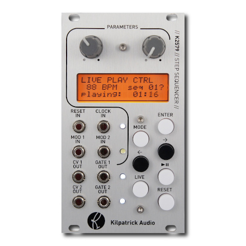
To further my interest in sequencer design I developed the K2579 Step Sequencer module. It is a two-track step sequencer with a number of unique processing functions, full MIDI control and CV inputs which allow many different parameters to be controlled in real-time.
The K2579 allows most functions to be changed in real-time which became my goal in all future designs. Unlike computer music systems, the K2579 can perform nearly all functions while the sequencer is running which includes modifying playback parameters, changing the sequence notes, as well as adjusting the sequence length and direction.
Find out more about K2579
K3020 Dual VCO (Kilpatrick Audio) - 2011
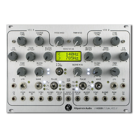
I embarked on the K3020 project with the goal of making the best analog oscillator for Eurorack modular synthesizers. At the time it was released it was one of the largest and most complete oscillator modules ever created. Each oscillator uses a triangle core architecture and has sine, triangle and ramp outputs. In addition it supports both exponential and linear pitch control, as well as being able to act as an LFO. The pulse section has three PWM circuits per channel which can be combined in unique ways to create very complex sounds. A voltage-controlled blend circuit allows the timbre to be changed without the need for a filter.
Through the use of a second oscillator channel and a number of cross-modulation functions, the K3020 allows for complete performances to be created with just the module itself. The entire signal path is analog, however all control and switching functions are digitally controlled for low switching noise and ultra-reliable operation. The centre section of the module contains a dual channel frequency counter that can be used to find the pitch down to 1Hz resolution.
Find out more about K3020
K1600 MIDI Converter (Kilpatrick Audio) - 2010
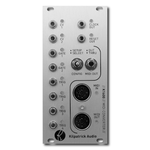
When the K1600 MIDI Converter was released there were virtually no serious MIDI to CV converter modules on the market, and virtually none that could operate in duo or polyphonic modes. The K1600 allows most types of MIDI signals to be automatically mapped to the outputs using a convenient learn mode function. With two CV/gate output pairs as well as clock and trigger outs, the K1600 can act as a powerful interface for controlling modular systems from MIDI keyboards or computers.
By using the MIDI THRU feature, multiple K1600 units can be daisy-chained together for polyphonic playing. Each module can be used to address a pair of channels in a polyphonic performance. In addition there are modes which allow CC, pitch bend, split keyboard and several other modes of operation.
Find out more about K1600
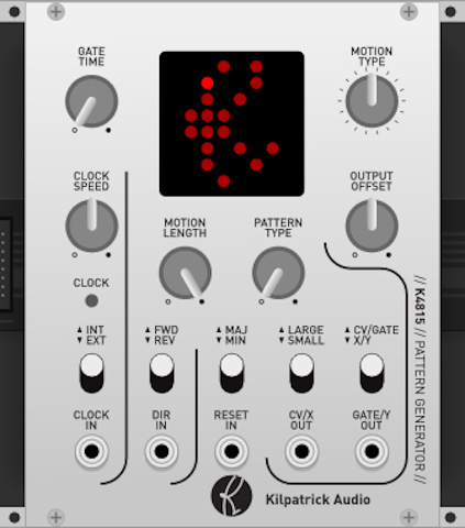
K4815 Pattern Generator (Kilpatrick Audio) - 2010
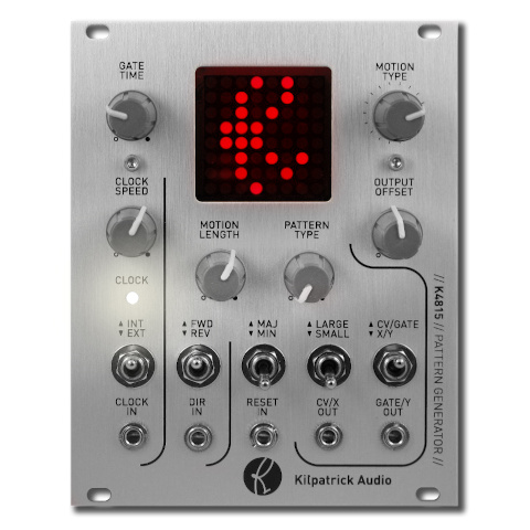
The K4815 Pattern Generator was my first synthesizer product. The original MIDI-only prototype was built in a plastic project box using a large LED matrix display found at a local electronics store. With a very simply set of controls and a basic pattern generating concept, I found that just about everyone who used it had a ton of fun with it. At the time I was working on a complete DIY modular synthesizer and found myself playing the same simple tunes on the keyboard for testing the modules. The idea to make the prototype into a proper module seemed logical, and after several months of hard work the first hand-built K4815 modules were ready! The K4815 has been in continous production for more than ten years.
The K4815 uses a simple concept where motions, scales and gate patterns are combined to create unexpected yet musically useful melodies and rhythms. Literally hundreds of thousands of combinations are possible. When looking for inspiration or just testing the sound of a synth patch, the K4815 can generate interesting content with minimal user input. I now offer a web-based editor tool which allows users to create their own basic content for those looking for different patterns, unusual scales, and so on.
Find out more about K4815
Guitar Effect Pedals (Kilpatrick Audio) - 2008-2009
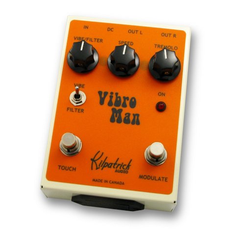
My first attempt at making music products came as I was still employed as a hardware designer for a digital advertising company. At night I worked in a small studio near my house to develop a line of digital guitar effects. This eventually resulted in five models. Some of these were featured in a 2010 issue of Premier Guitar magazine where the Vibro Man (pictured) was given the editor's pick award.
Much of what I learned developing these products ended up being used later in other projects. I even developed a set of DSP development tools for the processor used in these designs since the vendor-supplied tools were not very good. These tools became the basis of a commercial DSP development tool which was available for many years and used by many other designers.
Blinkenlights Stereoscope (Project Blinkenlights) - 2008

In 2008 I was fortunate to work on the Project Blinkenlights project Stereoscope, which was presented in Toronto as the headline presentation of that year's Nuit Blanche art festival. My friends and I (three of us) volunteered to help the German team. They tasked us with writing two major software components: a multi-streaming video mixer / compositor, and a telephone-based game system.
Stereoscope was the third and largest incarnation of Blinkenlights. It had previously been presented in Paris and Berlin both on a smaller scale. Stereoscope was presented at Toronto City Hall where all of approx. 960 large office windows were covered with translucent material and illuminated from behind with a 150W halogen lamp. All of the lamps used custom-designed dimmers developed in Germany.
My team and I developed code which used the existing Blinkenlights network protocol and offered new functions such as layers with transparency, virtual framebuffers, and system monitoring functions. We also developed a telephone game server which allowed games to be played on the screens by calling various local telephone numbers to play the games via DTMF tones. My custom Asterisk server ran on FreeBSD and supported eight phone numbers linked to different games.